다음은 관련된 이론 내용을 예쁜 그림과 설명한 사이트입니다.
https://www.scratchapixel.com/lessons/mathematics-physics-for-computer-graphics/lookat-function
Placing a Camera: the LookAt Function
Lesson summary:
www.scratchapixel.com
Contents
Keywords: Matrix, LookAt, camera, cross product, transformation matrix, transform, camera-to-world, look-at, Gimbal lock.
In this short lesson we will study a simple but useful method for moving 3D cameras around. You won't understand this lesson easily if you are not familiar with the concept of transformation matrix and cross product between vectors. Hopefully if that's not already the case, we recommend you to read the lesson called Geometry (entirely).
이 단원에서는 3D 카메라를 움직이는 간단하면서도 유용한 방법을 공부합니다. 벡터 간의 변환 행렬 및 교차 곱의 개념에 익숙하지 않은 경우이 단원을 쉽게 이해할 수 없습니다. 희망 사항이 아니라면, 기하학이라는 교훈을 읽어 보시기 바랍니다.
Moving the Camera
Being able to move the camera in a 3D scene is really essential. However in most of the lessons from Scratchapixel we usually set the camera position and rotation in space (remember that cameras shouldn't be scaled), using a 4x4 matrix which is often labelled camToWorld. Remember that the camera in its default position is assumed to be centred at the origin and aligned along the negative z-axis. This is explained in detail in the lesson Ray Tracing: Generating Camera Rays. However, using a 4x4 matrix to set the camera position in the scene, is just not very friendly, unless we can access a 3D animation system such as for example Maya or Blender to set the camera and export its transformation matrix.
3D 장면에서 카메라를 움직일 수 있다는 것은 정말로 중요합니다. 그러나 Scratchapixel에서 나온 대부분의 수업에서 대개 camToWorld라는 4x4 행렬을 사용하여 공간에서 카메라 위치와 회전을 설정합니다 (카메라의 크기를 조정하면 안 됨). 기본 위치에있는 카메라는 원점의 중심에 있고 음의 z 축을 따라 정렬되어 있다고 가정합니다. 자세한 내용은 레이 트레이싱 : 카메라 광선 생성을 참조하십시오. 그러나 4x4 매트릭스를 사용하여 장면에서 카메라 위치를 설정하는 것은 Maya 나 Blender와 같은 3D 애니메이션 시스템에 액세스하여 카메라를 설정하고 변형 행렬을 내보낼 수있는 경우가 아니면 친숙하지 않습니다.
Hopefully, we can use another method which is better than setting up the matrix directly and doesn't require an editor (though this is of course always better). This technique doesn't really have a name but programmers usually refer to it to it as the Look-Atmethod. The idea of the method is simple. In order to set a camera position and orientation, all you really need is a point to set the camera position in space which we will refer to as the from point, and a point that defines what the camera is looking at. We will refer to this point as the to point.
바라건대, 우리는 행렬을 직접 설정하는 것보다 낫고 편집기를 필요로하지 않는 다른 방법을 사용할 수 있습니다 (물론 이것은 항상 더 좋지만). 이 기술은 실제로 이름이 없지만 프로그래머는 일반적으로 Look-Atmethod로 참조합니다. 이 방법의 아이디어는 간단합니다. 카메라의 위치와 방향을 설정하기 위해 필요한 것은 공간에서 카메라 위치를 설정하는 지점이며, 여기서 점이라고도 부르는 점과 카메라가보고있는 점을 정의하는 점입니다. 이 지점을 to 지점이라고 부릅니다.

What's interesting is that from this pair of points, we can create a camera 4x4 matrix as we will demonstrate in this lesson.
흥미로운 점은이 점 쌍에서 카메라 4x4 매트릭스를 만들 수 있다는 것입니다.
The camera is aligned along the negative z-axis. Does it mean I need to rotate the camera by 180 degrees along the y-axis or scale it up by -1 along the z-axis? Not at all. Transforming a camera is no different from transforming any other object in a scene. Keep in mind that in ray-tracing, we build the primary rays as if the camera was located in its default position. This is explained in the lesson Ray Tracing: Generating Camera Rays. This is when we actually reverse the direction of the rays. In other words, the z-coordinates of the rays' directions at this point are always negative: the camera in its default position, looks down along the negative z-axis. Those primary rays are then transformed by the camera-to-world matrix. Therefore, there is no need to account for the default orientation of the camera when the 4x4 camera-to-world matrix is built.
카메라가 음의 z 축을 따라 정렬됩니다. y 축을 따라 카메라를 180도 회전 시키거나 z 축을 따라 -1만큼 확대 할 필요가 있다는 것을 의미합니까? 전혀. 카메라를 변형하는 것은 장면의 다른 객체를 변형하는 것과 다르지 않습니다. 광선 추적에서 카메라가 기본 위치에있는 것처럼 기본 광선을 만듭니다. 이는 레이 트레이싱 : 카메라 광선 생성에 설명되어 있습니다. 이것은 우리가 광선의 방향을 실제로 뒤집을 때입니다. 즉,이 지점에서 광선의 방향의 z 좌표는 항상 음수입니다. 기본 위치의 카메라는 음의 z 축을 따라 아래를 보입니다. 그런 다음 이들 기본 광선은 카메라 - 월드 매트릭스에 의해 변형됩니다. 따라서 4x4 카메라 - 월드 매트릭스가 구축 될 때 카메라의 기본 방향을 고려할 필요가 없습니다.
The Method

Figure 1: the local coordinate system of the camera aimed at a point.

Figure 2: computing the forward vector from the position of the camera and target point.
Remember that a 4x4 matrix encodes the 3-axis of a Cartesian coordinate system. Again if this is not obvious to you, please read the lesson on Geometry. Remember that there are two conventions you need to pay attention to when you deal with matrices and coordinate systems. For matrices you need to choose between the row-major and column-major representation. At Scratchapixel, we use a row-major notation. As for coordinate system, you need to choose between a right-hand and left-hand coordinate system. We use a right-hand coordinate system. The fourth row of the 4x4 matrix (in a row-major matrix) encodes the translation values.
4x4 행렬은 데카르트 좌표계의 3 축을 인코딩한다는 것을 기억하십시오. 다시 한번 이것이 분명하지 않다면, 기하학에 대한 공과를 읽으십시오. 행렬 및 좌표계를 처리 할 때주의해야 할 두 가지 규칙이 있음을 기억하십시오. 행렬의 경우 행 주요 및 열 주요 표현 중에서 선택해야합니다. Scratchapixel에서 행 주요 표기법을 사용합니다. 좌표계는 오른손 및 왼손 좌표계 중에서 선택해야합니다. 우리는 오른손 좌표계를 사용합니다. 4x4 행렬의 네 번째 행 (행 - 주요 행렬에서)은 변환 값을 인코딩합니다.

How you name the axis of a Cartesian coordinate system depends on your preference, you can call them x, y and z but in this lesson for clarity, we will name them right(for x-axis), up (for the y-axis) and forward for the (z-axis). This is illustrated in figure 1. The method from building a 4x4 matrix from the from-to pair of points can be broken down in four steps:
데카르트 좌표계의 축 이름은 선호도에 따라 다르며, x, y, z라고 부를 수 있습니다.이 레슨에서는 명확하게하기 위해 오른쪽 (x 축), 위쪽 (y 축) ) 및 앞으로 (z 축). 그림 1에 나와 있습니다. 시작점에서 끝점까지의 4x4 행렬을 작성하는 방법은 4 단계로 나눌 수 있습니다.
- Step 1: compute the forward axis. In figure 1 and 2 it is quite easy to see that the forward axis of the camera local coordinate system is aligned along the line segment defined by the points from and to. A little bit of geometry suffices to compute this vector. You just need to normalize the vector To−From (mind the direction of this vector: it is To−From not From−To). This can be done with the following code snippet:
- 그림 1과 2에서 카메라 로컬 좌표계의 앞으로 축은 시작점과 끝 점으로 정의 된 선분을 따라 정렬됩니다. 이 벡터를 계산하려면 약간의 기하학 만 있으면 충분합니다. 벡터 To-From을 표준화하면됩니다 (To-From not-To). 다음 코드 스 니펫을 사용하여이 작업을 수행 할 수 있습니다.
-
Vec3f forward = Normalize(from - to);
We found one vector. Two left! - Step 2: compute the right vector. Recall from the lesson on Geometry that Cartesian coordinates are defined by three unit vectors that are perpendicular to each other. We also know that if we take two vectors A and B, they can be seen as lying into a plane, and that the cross product of these two vectors create a third vector C perpendicular to that plane and thus also obviously perpendicular to A and B. We can use this property to create our right vector. This idea here is to use some arbitrary vector and compute the cross vector between the forward vector and this arbitrary vector. The result is a vector that is necessarily perpendicular to the forward vector and that can be used in the construction of our Cartesian coordinate system as the right vector. The code for computing this vector is simple since it only implies a cross product between the forward vector and this arbitrary vector:
- 기하학에 대한 교훈에서 직교 좌표는 서로 수직 인 세 개의 단위 벡터로 정의됩니다. 우리는 두 개의 벡터 A와 B를 취하면 평면에 놓여있는 것으로 볼 수 있고이 두 벡터의 외적은 그 평면에 수직 인 세 번째 벡터 C를 만들고 따라서 A와 B에도 명백하게 수직임을 알 수 있습니다 이 속성을 사용하여 오른쪽 벡터를 만들 수 있습니다. 이 아이디어는 임의의 벡터를 사용하고 포워드 벡터와이 임의 벡터 간의 교차 벡터를 계산하는 것입니다. 결과는 앞으로 벡터에 반드시 수직이며 오른쪽 벡터로 직교 좌표계를 만드는 데 사용할 수있는 벡터입니다. 이 벡터를 계산하기위한 코드는 순방향 벡터와이 임의의 벡터 사이의 외적을 의미하기 때문에 간단합니다.
-
Vec3f right = crossProduct(randomVec, forward);

Figure 3: the vector (0,1,0) is in the plane defined by the forward and up vector. The vector perpendicular to this plane is thus the right vector.
The question is now, how do we choose this arbitrary vector? Well this vector can't really be totally arbitrary which is the reason why we wrote the word in italic. Think about this: if the forward vector is (0,0,1), then the right vector ought to be (1,0,0). This can only be done if we choose as our arbitrary vector, the vector (0,1,0). Indeed: (0,1,0) x (0,0,1) = (1,0,0) where the sign x here accounts for the cross product. Remember that the equations to compute the cross-product are:
문제는 이제 우리가이 임의의 벡터를 어떻게 선택 하는가입니다. 글쎄,이 벡터는 실제로 완전히 임의적 일 수는 없으므로 우리가 이탤릭체로 단어를 썼다. 이것에 대해서 생각해보십시오 : 만일 forward 벡터가 (0, 0, 1)이라면, right vector는 (1,0,0)이되어야합니다. 이것은 임의의 벡터 인 벡터 (0,1,0)를 선택하는 경우에만 수행 할 수 있습니다. 실제로 : (0,1,0) x (0,0,1) = (1,0,0) 여기서 x 기호는 여기에 교차 곱을 설명합니다. 교차 제품을 계산하는 방정식은 다음과 같습니다.
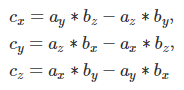
where a and b are two vectors and c is the result of the cross product of a and b. When you look at figure 3, you can also notice that regardless of the forward vector's direction, the vector perpendicular to the plane defined by the forward vector and the vector (0,1,0) is always the right vector of the camera's Cartesian coordinate system. That is because the up vector of that coordinate system lies within that same plane as showed in figure 4. That's great because the vector (0,1,0) can clearly be used in place of what we called earlier our arbitrary vector.
여기서 a와 b는 두 벡터이고 c는 a와 b의 외적 결과이다. 그림 3을 보면 앞으로 벡터의 방향에 관계없이 forward 벡터와 벡터 (0,1,0)에 의해 정의 된 평면에 수직 인 벡터가 항상 카메라의 직교 좌표의 right 벡터임을 알 수 있습니다 체계. 왜냐하면 좌표계의 위쪽 벡터가 그림 4에 표시된 것과 같은 평면 내에 있기 때문입니다. 이는 벡터 (0,1,0)가 우리가 임의의 벡터를 먼저 호출 한 위치 대신 명확하게 사용할 수 있기 때문에 좋습니다.
Note also from that observation that the right vector always lie within the xz-plane. How come you may ask? If the cameras has a roll wouldn't the right vector be in a different plane? That's actually true, but applying a roll to the camera is not something you can do directly with the look-at method. To add a camera roll, you would first need to create a matrix to roll the camera (rotate the camera around the z-axis) and then multiply this matrix by the camera-to-world matrix built with the look-at method.
-
그 관찰에서 오른쪽 벡터가 항상 xz 평면 내에 놓여 있음을 주목하십시오. 어떻게 물어 보시겠습니까? 카메라에 롤이 있으면 오른쪽 벡터가 다른 평면에 있지 않을까요? 실제로는 사실이지만 카메라에 롤을 적용하는 것은 look-at 방법으로 직접 할 수있는 것이 아닙니다. 카메라 롤을 추가하려면 먼저 카메라를 굴리려는 행렬을 만들고 (카메라를 z 축을 중심으로 회전) look-at 메서드로 작성된 카메라 - 월드 (camera-to-world) 행렬에이 행렬을 곱해야합니다.
Finally, here is the code to compute the right vector:
Vec3f tmp(0, 1, 0);
Vec3f right = crossProduct(Normalize(tmp), forward);Note that we normalize the arbitrary vector just in case you would actually be using a vector that is different from (0,1,0). So in order to be on the safe side, we will normalise it. Also pay attention to the order of the vectors in the cross product. Keep in mind that the cross product is not commutative (it is actually anti-commutative, check the lesson on Geometry for more details). The best mnemonic way of remembering the right order, is to think of the cross product of the forward vector (0,0,1) with the up vector (0,1,0) we know it should give (1,0,0) and not (-1,0,0). If you know the equations of the cross-product, you should easily find out that the order is up×forward and not the other way around. Great we have the forward and right vector. How do now find the up vector?
실제로 (0,1,0)과 다른 벡터를 사용하려는 경우에 대비하여 임의 벡터를 정규화합니다. 따라서 안전한면에 있기 위해 우리는 그것을 정상화 할 것입니다. 또한 교차 제품에서 벡터의 순서에주의하십시오. 십자가 제품은 교환 가능하지 않습니다 (사실은 반 보수입니다. 자세한 내용은 Geometry에서 강의를 확인하십시오). 올바른 순서를 기억하는 최선의 니모닉 방법은 앞으로 벡터 (0,0,1)의 교차 곱을 우리가 알아야하는 상향 벡터 (0,1,0)로 생각하는 것입니다 (1,0,0 )가 아니라 (-1,0,0). 교차 제품의 방정식을 알고 있다면 순서가 전방에 있고 전진하지 않은 것을 쉽게 알아 내야합니다. 위대한 우리는 앞으로 및 오른쪽 벡터 있습니다. 어떻게 상향 벡터를 찾을 수 있습니까? - Step 4: compute the up vector. Well this is very simple, we have two orthogonal vectors, the forward and right vector, so computing the cross product between this two vectors will just give us the missing third vector, the up vector. Note that if the forward and right vector are normalized, then the resulting up vector computed from the cross product will be normalized too:
- 이것은 매우 간단합니다. 우리는 두 개의 직교 벡터 인 전진 벡터와 우 벡터를 가지므로이 두 벡터 사이의 외적을 계산하면 누락 된 세 번째 벡터 인 상향 벡터를 얻을 수 있습니다. 앞으로 및 오른쪽 벡터가 정규화되면 교차 곱에서 계산 된 결과 벡터가 정규화됩니다.
-
Vec3f up = crossProduct(forward, right);
Here again, you need to be careful about the order of the vectors involved in the cross product. Great we now have the three vectors defining the camera coordinate system. Let's now build our final 4x4 camera-to-world matrix.
여기서도 교차 상품에 포함 된 벡터의 순서에주의해야합니다. 이제 카메라 좌표계를 정의하는 세 개의 벡터가 있습니다. 마지막으로 4x4 카메라 - 월드 매트릭스를 제작 해 보겠습니다.
- Step 4: set the 4x4 matrix using the right, up and forward vector as from point.
- 4 단계 : 4x4 행렬을 point에서와 같이 오른쪽, 위쪽 및 아래쪽 벡터를 사용하여 설정합니다.
- All there is to do to complete the process is to build the camera-to-world matrix itself. For that, we just replace each row of the matrix with the right data:
- 이 과정을 완료하는 데 필요한 것은 카메라에서 월드 행렬 자체를 작성하는 것입니다. 이를 위해 행렬의 각 행을 올바른 데이터로 바꿉니다.
- Row 1: replace the first three coefficients of the row with the coordinates of the right vector,
- 행의 처음 세 계수를 오른쪽 벡터의 좌표로 바꾸고,
- Row 2: replace the first three coefficients of the row with the coordinates of the up vector,
- 행의 처음 세 계수를 위쪽 벡터의 좌표로 바꿉니다.
- Row 3: replace the first three coefficients of the row with the coordinates of the forward vector,
- 행의 처음 세 계수를 순방향 벡터의 좌표로 바꾸고,
- Row 4: replace the first three coefficients of the row with the coordinates of the from point.
- 행의 처음 세 계수를 시작 지점의 좌표로 바꿉니다.
Again, if you are unsure about why we do that, check the lesson on Geometry. Finally here is the source code of the complete function. It computes and return a camera-to-world matrix from two arguments, the from and to points. Note that the function third parameter (called tmp in the following code) is the arbitrary vector used in the computation of the right vector. It is set with the default value of (0,1,0) but it can be changed if desired (hence the need to normalize it when used).
다시 말하지만 왜 우리가 그렇게하는지 확신이 없다면 기하학에 대한 강의를 확인하십시오. 마지막으로 완전한 함수의 소스 코드가 있습니다. 그것은 from과 to의 두 인수에서 camera-to-world 행렬을 계산하여 반환합니다. 세 번째 매개 변수 (다음 코드에서 tmp라고 함)는 오른쪽 벡터 계산에 사용되는 임의의 벡터입니다. 기본값 (0, 1, 0)로 설정되지만 원하는 경우 변경할 수 있습니다 (따라서 사용할 때 표준화해야 함).
Matrix44f lookAt(const Vec3f& from, const Vec3f& to, const Vec3f& tmp = Vec3f(0, 1, 0))
{
Vec3f forward = normalize(from - to);
Vec3f right = crossProduct(normalize(tmp), forward);
Vec3f up = crossProduct(forward, right);
Matrix44f camToWorld;
camToWorld[0][0] = right.x;
camToWorld[0][1] = right.y;
camToWorld[0][2] = right.z;
camToWorld[1][0] = up.x;
camToWorld[1][1] = up.y;
camToWorld[1][2] = up.z;
camToWorld[2][0] = forward.x;
camToWorld[2][1] = forward.y;
camToWorld[2][2] = forward.z;
camToWorld[3][0] = from.x;
camToWorld[3][1] = from.y;
camToWorld[3][2] = from.z;
return camToWorld;
}
The Look-At Method Limitation
The method is very simple and works generally well. Though it has an Achilles heels (a weakness). When the camera is vertical looking straight down or straight up, the forward axis gets very close to the arbitrary axis used to compute the right axis. The extreme case is of course when the froward axis and this arbitrary axis are perfectly parallel e.g. when the forward vector is either (0,1,0) or (0,-1,0). Unfortunately in this particular case, the cross product fails producing a result for the right vector. There is actually no real solution to this problem. You can either detect this case, and choose to set the vectors by hand (since you know what the configuration of the vectors should be anyway). A more elegant solution can be developed using quaternion interpolation.
이 방법은 매우 간단하며 일반적으로 잘 작동합니다. 그것에는 Achilles 발 뒤꿈치가있다 (약점). 카메라가 수직으로 똑바로 내려다 보거나 직선으로 보일 때, 앞으로 축은 오른쪽 축을 계산하는 데 사용 된 임의의 축에 매우 가깝게됩니다. 극단적 인 경우는 훼손축과이 임의의 축이 완전히 평행 할 때 물론이다. 순방향 벡터가 (0,1,0) 또는 (0, -1,0) 일 때. 불행히도이 특별한 경우에는 교차 곱이 올바른 벡터에 대한 결과를 생성하지 못합니다. 실제로이 문제에 대한 실제 해결책은 없습니다. 이 경우를 감지하고 손으로 벡터를 설정하도록 선택할 수 있습니다 (벡터의 구성이 어쨌든 있어야한다는 것을 알기 때문에). 보다 우아한 솔루션은 쿼터니온 보간을 사용하여 개발할 수 있습니다.
'Etc' 카테고리의 다른 글
| adMob - reward, libgdx (0) | 2019.11.30 |
|---|---|
| adMob - interstitial, libgdx (0) | 2019.11.30 |
| adMob - banner, libgdx (0) | 2019.11.23 |
| 카메라 lookAt 함수의 이용 - 예제, 활용법(example, how to) (0) | 2019.11.12 |
| 카메라 lookAt 함수의 이용 - Yaw, Pitch, Roll (0) | 2019.11.12 |


댓글